-
- CNC Panel SawCNC Router MachineAutomatic Edge Banding MachineSix Sided CNC Drilling Machine
- Application
![news]()
How CNC Router Machines Cut Metal, Wood and Plastic
Views: 0 Author: Site Editor Publish Time: 2026-07-25 Origin: Site
![facebook sharing button]()
![twitter sharing button]()
![line sharing button]()
![wechat sharing button]()
![linkedin sharing button]()
![pinterest sharing button]()
![whatsapp sharing button]()
![sharethis sharing button]()
A common misconception in manufacturing is that CNC routers possess universal capabilities across all substrates. While a machine's theoretical capacity might suggest it can handle anything from soft foam to rigid metals, practical production reliability tells a different story. Understanding how to properly evaluate CNC Router Cutting Materials requires a fundamental mental shift. Unlike additive manufacturing processes like 3D printing, subtractive CNC routing demands careful consideration of mechanical resistance, precise toolpaths, and aggressive material removal rates.
Misaligning machine specifications with your intended production materials introduces severe operational risks. Pushing a lightweight gantry to carve dense materials without adequate spindle torque or frame rigidity leads directly to excessive tool wear, scrapped parts, and catastrophic machine damage. This guide serves as a technical evaluation framework to help you understand exact material tolerances, tooling requirements, and operational trade-offs. By analyzing these factors, you can make evidence-based procurement decisions that align perfectly with your production demands.
Spindle Dynamics Dictate Substrate: High-RPM, lower-torque router spindles excel in soft materials but require strict feed-and-speed management for metals to avoid chatter.
Thermal Management is Critical for Plastics: Successful plastic CNC machining relies entirely on chip evacuation to prevent material melting and tool welding.
Rigidity Limits Metal Capabilities: While aluminum cutting CNC operations are viable, routers lack the structural mass of CNC mills, restricting them to non-ferrous, soft metals.
Tooling Drives ROI: Material compatibility is ultimately governed by selecting the correct flute geometry (e.g., O-flute for plastics, up-cut/down-cut compression for wood composites).
The Mechanics of CNC Router Cutting Materials
A successful cut across any substrate is defined by strict criteria: precise dimensional accuracy, a clean edge finish, and an absolute lack of thermal damage. Achieving these outcomes requires a deep understanding of Cartesian coordinate mechanics. CNC routers operate on X, Y, and Z axes to execute precise material removal. The gantry moves along the X and Y axes to position the spindle over the workpiece, while the Z-axis controls the depth of the cut. Standard 3-axis operations handle flat sheet goods efficiently, whereas advanced machines incorporate rotational capabilities for complex, multi-sided geometries.
The mechanical difference between CNC routers and CNC mills fundamentally dictates material limitations. Routers utilize high-speed, low-torque spindles designed to slice rapidly through yielding materials. Mills rely on low-speed, high-torque spindles to power through dense ferrous metals. Attempting to force a high-RPM router spindle through hard steel will instantly stall the motor or shatter the tooling. You must match the spindle dynamics to the mechanical resistance of the substrate.
Frame rigidity and bed size play equally critical roles in cut quality. Gantry deflection and vibration during high-impact material processing ruin surface finishes and destroy dimensional tolerances. Bed sizes range from compact hobbyist benchtops to massive industrial footprints exceeding 4'x4' capacities. The bed size dictates the scale, weight, and sheet capacity of compatible stock. Transitioning from carving soft foams to routing denser materials establishes a strict baseline requirement for heavy-duty, welded steel frames to absorb the increased mechanical resonance.
When evaluating a machine's mechanical limits, operators must look at the linear guide rails and ball screws. Heavy-duty applications require robust, square linear bearings that can handle high load capacities in all directions. Lighter machines often use round guide rails, which are prone to deflection under heavy cutting forces. The drive system also matters. Rack and pinion drives offer high speed and acceleration for large format routers, while ball screws provide superior precision for smaller, intricate work.
Wood Routing Process: Hardwoods, Softwoods, and Composites
Approaching the wood routing process requires categorizing materials into natural woods, engineered composites like MDF and plywood, and secondary soft materials such as modeling foams. Each category demands specific tooling strategies based on grain direction and density. Natural woods possess unpredictable grain structures that require sharp cutting edges to prevent splintering. Engineered composites lack natural grain but contain abrasive binders that rapidly degrade tooling.
Tool selection must account for material thickness and hold-down methods. Compression bits are absolutely necessary to prevent tear-out on delicate veneered plywood. These bits combine up-cut and down-cut geometries, pushing the top and bottom faces of the material toward the center of the cut to leave a flawless edge. Standard up-cut bits clear chips efficiently but can lift the material off the bed, requiring robust vacuum hold-down systems. Down-cut bits push chips into the cut path, securing the material against the table but risking heat buildup if feed rates are too slow.
Managing the abrasive nature of glues in MDF and particleboard is a constant challenge. High-volume composite routing requires evaluating the return on investment for different tooling materials. Carbide-tipped bits offer a balance of cost and durability, while solid carbide provides superior longevity. For extreme production environments, polycrystalline diamond (PCD) tooling delivers unmatched wear resistance against harsh composite binders.
Before carving expensive hardwoods like cherry or walnut, prototyping complex 3D toolpaths is a standard risk mitigation strategy. High-density polyurethane foams or low-cost machinable wax serve as excellent, low-risk materials for verifying toolpath accuracy. Incorrect feed rates during hardwood routing frequently cause friction burns. You must optimize toolpaths to maintain a constant chip load, ensuring the bit shears the material cleanly rather than rubbing against it and generating excessive heat.
To successfully prototype and execute a wood routing project, follow these practical steps:
Verify the toolpath simulation in your CAM software to identify any potential collisions or excessive plunge rates.
Secure a piece of low-cost machinable wax or high-density foam to the router bed using double-sided tape or light clamps.
Run the program at 100% feed rate to test the actual machine dynamics and observe the surface finish.
Inspect the prototype for dimensional accuracy using digital calipers.
Adjust the stepover and feed rates in the CAM software based on the prototype results before loading the final hardwood stock.
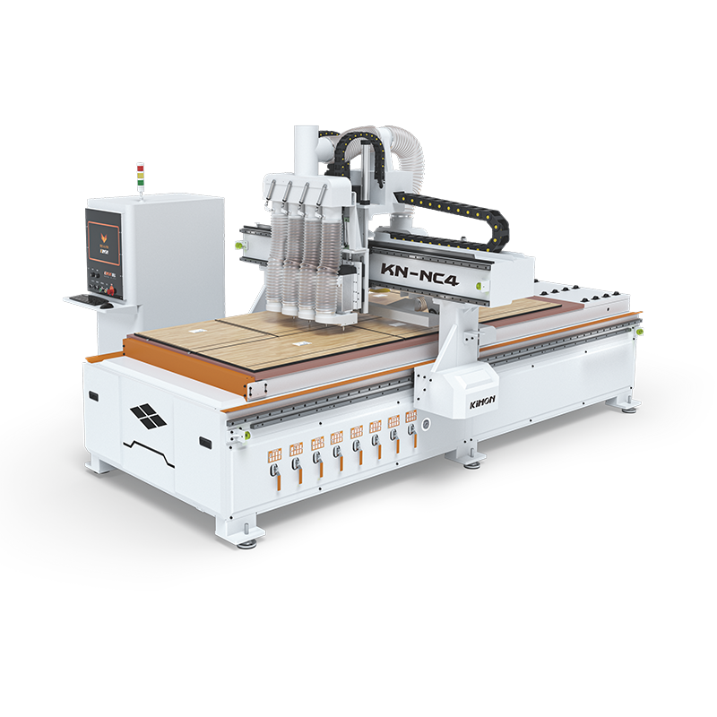
![CNC Router Machine]()
Plastic CNC Machining: Thermoplastics and Acrylics
Evaluating features-to-outcomes in plastic cnc machining focuses heavily on the relationship between feed rates, spindle speeds, and thermal dynamics. Plastics are highly sensitive to heat. Successful routing relies on generating the correct chip load—the physical size of the material removed by each flute per revolution. Larger chips act as heat sinks, pulling thermal energy away from the cut zone. If feed rates are too slow relative to spindle RPM, the bit generates friction instead of chips.
Failing to manage heat and chip evacuation results in catastrophic material failure. As the plastic heats up, it melts and re-welds itself directly behind the bit. This ruins the workpiece and frequently snaps the tooling. You must maintain aggressive feed rates to ensure chips are constantly ejected from the cutting channel.
Tooling geometries must be tailored to specific plastic types. Soft plastics like HDPE and UHMW respond best to single-flute O-flute solid carbide bits. The open flute design provides maximum clearance for rapid chip ejection. Brittle plastics, such as cast acrylic and polycarbonate, require specialized bits designed to shear the material cleanly without inducing micro-fractures along the cut edge.
Implementation risks in plastic routing include stress cracking, crazing, and warpage. Proper workholding is essential to reduce vibration, which exacerbates edge chipping in brittle acrylics. Vacuum tables provide the most uniform hold-down force for flat plastic sheets. If internal stresses cause the material to warp after machining, post-machining annealing processes may be necessary to stabilize the final parts.
Plastic Type
Characteristics
Recommended Tooling
Primary Machining Challenge
HDPE / UHMW
Soft, yielding, low melting point
Single-flute O-flute (Up-cut)
Material melting and chip welding
Cast Acrylic
Brittle, prone to chipping
Single or double-flute O-flute (Specialized acrylic geometry)
Edge crazing and micro-fractures
Polycarbonate
Tough, impact-resistant
Single-flute O-flute
Vibration and chatter during heavy cuts
PVC
Dense, produces toxic fumes if burned
O-flute or V-bits for engraving
Maintaining consistent chip load to prevent burning
Aluminum Cutting CNC and Soft Metals
Cutting metal on a machine designed primarily for softer substrates presents unique engineering challenges. Standard CNC routers struggle with hard, ferrous metals like steel and iron due to a fundamental lack of gantry rigidity and insufficient spindle torque at low RPMs. However, soft non-ferrous options—specifically aluminum, brass, and bronze—are entirely viable with optimized setups and strict operational parameters.
The physics of an aluminum cutting cnc operation introduce the momentum and inertia risk, often referred to as the unstoppable tool. Once a high-speed spindle is in motion, the machine will attempt to reach its programmed coordinate destination regardless of mechanical resistance. If the bit plunges too deeply into an aluminum billet, the resulting crash can shatter the tool, destroy the spindle bearings, or bend the gantry out of square. Physical limit switches, immediate emergency stops, and crash-sensing electronics are critical necessities to prevent catastrophic damage.
Optimizing feeds and speeds for aluminum and brass requires a distinct decision framework. You must utilize shallow depths of cut combined with higher feed rates. This approach maintains the necessary chip load without stalling the low-torque spindle. Adaptive clearing toolpaths are highly recommended, as they maintain a constant tool engagement angle, preventing sudden spikes in mechanical load.
Lubrication and coolant strategies are non-negotiable when routing aluminum. Minimum Quantity Lubrication and mist coolant systems apply a fine spray of cutting fluid directly to the tool interface. This reduces friction and prevents the aluminum from galling and welding to the cutter flutes. Dry routing with high-pressure air blasts is an alternative, but it requires massive airflow to clear chips instantly before they can be re-cut.
When setting up an aluminum job, operators must pay close attention to the alloy grade. 6061-T6 aluminum machines beautifully on a router because it produces distinct, brittle chips that evacuate easily. Softer alloys like 3003 or 5052 are gummy and prone to wrapping around the end mill. Adjusting the spindle speed and feed rate based on the specific alloy temper is a mandatory step for successful metal routing.
Evaluating Material Compatibility and Machine Specifications
Balancing machine features against your primary material needs determines overall production success. material compatibility dictates the specific workholding solutions and extraction systems required for your shop floor.
Workholding solutions vary drastically by substrate. Vacuum tables excel at securing large, flat sheet goods like plywood, MDF, and plastic sheets. The uniform downward pressure prevents the material from bowing during the cut. However, vacuum systems are generally ineffective for smaller, thicker metal billets. Routing heavy-cut setups in aluminum requires mechanical clamping, step blocks, or dedicated T-slot extrusions to physically lock the stock to the machine bed.
Extraction needs also diverge based on the material being processed. High-CFM dust collection systems are mandatory for MDF and wood routing to capture fine, airborne particulates that pose respiratory hazards. Conversely, routing metal and heavy plastics generates large, heavy chips that clog standard dust collectors. These applications require specialized enclosures, chip augers, or high-velocity air blasts directed into dedicated collection bins.
Spindle power is another major factor. A 2.2kW spindle might handle light wood and plastic engraving, but production-level cabinet making or aluminum milling demands 5kW to 9kW spindles. Higher power allows for larger diameter tooling and faster material removal rates without bogging down the motor. Always match the spindle power to the thickest, densest material you plan to cut regularly.
Conclusion
A CNC router's ability to cut metal, wood, and plastic is not absolute. It is entirely contingent on strict adherence to material-specific tooling, optimized feeds and speeds, and baseline machine rigidity. If your production volume consists of 80% wood and plastic with occasional aluminum brackets, a heavy-duty CNC router is the optimal choice. If your operations demand 80% metal processing, you must pivot your evaluation to a dedicated CNC mill.
Audit your primary material dimensions and daily production volumes to determine necessary bed size and gantry rigidity.
Request physical sample cuts from manufacturers using your specific substrates before finalizing any machine purchase.
Consult with a dedicated tooling specialist to calculate exact cycle times and establish baseline feed-and-speed parameters for your materials.
Evaluate your facility's capacity for specialized extraction systems, comparing high-CFM dust collection against mist coolant requirements.
FAQ
Q: Can a CNC router cut steel or hard metals?
A: No, standard CNC routers lack the necessary frame rigidity and low-speed spindle torque required to cut ferrous metals like steel. Attempting to route steel will cause severe chatter, destroy the tooling, and potentially damage the machine gantry. Steel requires the mass and power of a dedicated CNC mill.
Q: What is the best router bit for plastic CNC machining?
A: Single-flute O-flute solid carbide bits are the industry standard for soft plastics. The open flute geometry provides maximum clearance for rapid chip evacuation, which is critical for pulling heat away from the cut zone and preventing the plastic from melting and re-welding.
Q: How thick of aluminum can an aluminum cutting CNC router process?
A: Overall material thickness is less of a barrier than the depth of cut per pass. A rigid CNC router can process thick aluminum plates by utilizing very shallow passes combined with high feed rates, provided the machine frame can absorb the mechanical vibration.
Q: How do you prevent burning during the wood routing process?
A: Burning is caused by friction when the bit rubs against the wood instead of cutting it. You prevent this by optimizing the chip load—either by increasing the feed rate or decreasing the spindle RPM—ensuring the bit shears the material cleanly and ejects the heat with the chips.
Q: What factors determine CNC router material compatibility?
A: Material compatibility is determined by the machine's spindle RPM range, overall gantry rigidity, available workholding solutions, and the specific flute geometries of the tooling used. Matching the machine's mechanical limits to the substrate's density is crucial.
Q: Do I need coolant to cut aluminum on a CNC router?
A: Yes, lubrication is highly recommended. Minimum Quantity Lubrication or mist coolant systems prevent aluminum from galling and welding to the cutter flutes. If cutting dry, high-pressure air blasts are mandatory to clear chips instantly from the toolpath.
Q: What safety features are critical when cutting metals vs softer woods?
A: Metal routing introduces high mechanical resistance. Physical limit switches, immediate emergency stops, and fast-acting feed-hold mechanisms are critical to halt the spindle instantly during a crash, preventing catastrophic damage to the tooling and machine frame.

![English]()
![zhifufuben]()