-
- CNC Panel SawCNC Router MachineAutomatic Edge Banding MachineSix Sided CNC Drilling Machine
- Application
![news]()
How Can a Furniture Panel Saw Improve Material Yield With Nesting Plans?
Views: 0 Author: Site Editor Publish Time: 2026-08-18 Origin: Site
![facebook sharing button]()
![twitter sharing button]()
![line sharing button]()
![wechat sharing button]()
![linkedin sharing button]()
![pinterest sharing button]()
![whatsapp sharing button]()
![sharethis sharing button]()
Material waste silently drains profitability in panel processing. Even a minor 2-3% drop in material yield compounds rapidly, eroding profit margins for operations ranging from small custom shops to fully automated factories. Manual cut-list planning and traditional cross-cutting methods consistently fall short. These outdated approaches result in excessive offcuts, poor grain matching, and highly inefficient use of expensive sheet goods. Operators are left guessing the best sequences, leading to costly errors and overflowing scrap bins.
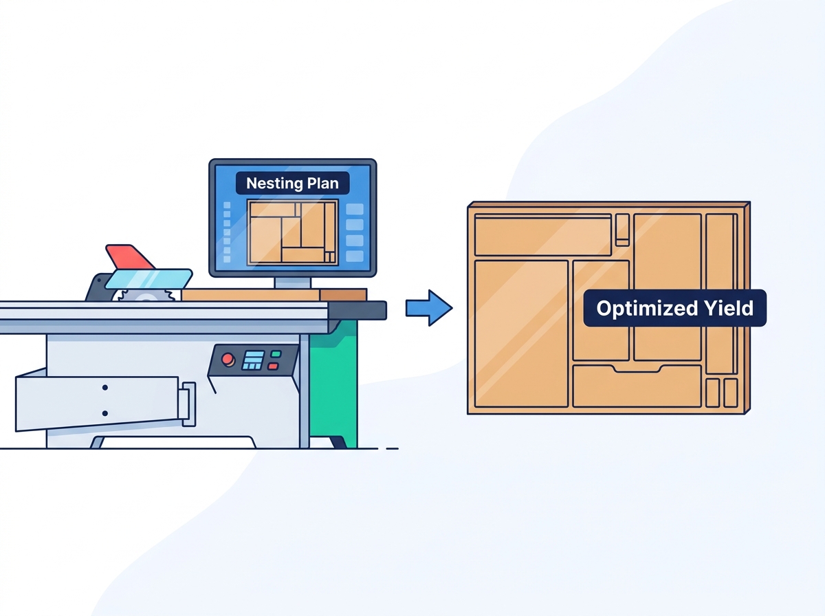
The definitive strategy for overcoming these inefficiencies involves integrating advanced nesting optimization software with a modern Furniture Panel Saw. This powerful combination mathematically arranges parts to maximize material utilization. It removes the guesswork from the shop floor, reduces overall cycle times, and provides a scalable foundation for production growth. By bridging the gap between intelligent software and precision cutting hardware, manufacturers can drastically reduce waste and improve their bottom line.
Key Takeaways
Algorithmic Efficiency: Nesting optimization software mathematically arranges parts to maximize sheet usage, frequently improving material yield by 10% to 15% compared to manual planning.
Hardware-Software Synergy: A high-performing cabinet panel cutting machine must possess seamless network integration to translate complex nesting algorithms into precise, executable cutting patterns.
Operational Trade-Offs: While optimizing yield, manufacturers must balance floor space requirements, material handling logistics, and the necessity of secondary machining operations (like CNC drilling).
Calibration is Critical: Yield improvements are voided if the saw is not perfectly squared and calibrated; precision maintenance by professional engineers is a non-negotiable requirement for tight-tolerance nesting.
The Economics of Material Yield in Panel Processing
Material yield represents the percentage of a raw sheet that ends up as a finished, usable part. Maximizing this percentage drives operational success in modern cabinetry and furniture manufacturing. Every square inch of discarded material represents lost revenue and wasted labor. Understanding the economics of panel processing requires analyzing the metrics used to measure success and the physical waste generated on the shop floor.
Calculating the True Cost of Offcuts and Waste
The financial impact of raw material waste extends far beyond the initial purchase of the board. You must calculate the waste percentage of the specific substrate being processed. Standard particleboard and MDF carry a lower baseline value, making minor waste slightly more tolerable. When cutting expensive wood veneers, high-gloss laminates, or specialized melamine, the financial penalty for poor yield increases exponentially. A 10% waste factor on premium walnut veneer sheets destroys project profitability before assembly even begins.
Different materials require specific yield strategies. High-gloss acrylics demand protective handling and wider margin allowances to prevent edge chipping. This inherently affects the nesting layout. Wood veneers require strict adherence to grain direction, limiting how parts rotate within the optimization software. These constraints naturally reduce maximum yield compared to solid-color melamine, where parts rotate freely in any orientation.
Hidden costs accompany waste disposal. Dumpster fees, transportation logistics, and labor hours spent managing scrap bins add significant overhead. Environmental compliance factors also play a role. Many regions enforce strict disposal regulations for engineered woods containing specific resins or adhesives. Reducing excess scrap at the source minimizes these compliance burdens and lowers overall waste management expenses.
To accurately track these losses, shop managers should implement a standardized waste audit:
Weigh the total scrap generated at the saw over a standard five-day production week.
Calculate the square footage of the discarded material based on the substrate density.
Compare the discarded square footage against the total square footage of raw sheets pulled from inventory.
Multiply the waste percentage by the monthly material spend to reveal the true financial leak.
Success Criteria for Yield Optimization
Evaluating a successful nesting implementation requires establishing clear, measurable baseline metrics. The most common metric is the target percentage of sheet utilization. A highly optimized layout typically achieves between 90% and 95% utilization, depending on part sizes and grain constraints. Another metric is the reduction in cutting time per sheet. Optimization should save material and streamline the physical cutting process.
Manufacturers must strike a balance between maximum yield and realistic cutting sequences. Software can generate incredibly complex patterns that squeeze an extra 1% of yield out of a sheet. If that pattern requires the operator to rotate the heavy panel six additional times and perform multiple intricate blind cuts, the labor time lost outweighs the material saved. Success means finding the sweet spot where high material utilization intersects with fast, ergonomic operator workflows.
![Furniture Panel Saw]()
How Nesting Plans Transform Furniture Panel Saw Operations
Transitioning from manual calculations to digital optimization fundamentally changes shop floor dynamics. Basic cut-list generators simply list the required parts and offer a rudimentary linear layout. True algorithmic software analyzes thousands of potential combinations in seconds to find the most efficient mathematical arrangement. Integrating this software with a furniture panel saw elevates the entire production line.
The Mechanics of Intelligent Material Optimization
Nesting algorithms process multiple variables simultaneously. The software analyzes exact part dimensions, required edgebanding allowances, and grain direction constraints. If a specific cabinet door requires vertical grain matching, the software locks that part's orientation during the calculation. It also factors in trim cuts. These are the initial cuts required to square the raw sheet and remove factory edge damage. Advanced systems also incorporate remnant management. If a large offcut remains after the required parts are nested, the software automatically logs that remnant back into inventory for future use, assigning it a unique barcode.
A core concept in this process is the requirement for guillotine cuts. Unlike free-form CNC routers that cut intersecting shapes using a spinning bit, a saw blade must pass completely through the material in a straight line. Nesting software designed for saws accommodates these linear cutting constraints. It organizes parts into continuous horizontal or vertical strips. The saw cuts these primary strips first. The operator then cross-cuts the strips into individual parts. The software calculates these continuous lines to minimize blade travel and prevent trapped parts. It sequences the cuts so the operator handles the heaviest pieces first, reducing physical fatigue over an eight-hour shift.
Bridging the Gap: Software to Saw
The workflow begins in the design office. Engineers use CAD/CAM software to design the furniture and generate a comprehensive parts list. This data exports directly into the optimization software. The optimizer runs its algorithms and produces a digital cutting map. This map transmits over the network directly to the saw's controller.
Once the data reaches the machine, barcode labeling systems become essential. As the operator completes a cut, the system prints a label containing the part number, dimensions, edgebanding instructions, and a barcode. The operator applies this label immediately. Downstream stations, such as edgebanders and point-to-point drilling centers, scan the barcode to pull up the exact machining program for that specific part. This seamless data transfer eliminates manual data entry errors and keeps production flowing smoothly.
Evaluating a Cabinet Panel Cutting Machine for Nesting Compatibility
Executing complex optimized plans requires robust hardware. Not all saws handle the rigorous demands of algorithmic nesting. When evaluating a cabinet panel cutting machine, you must assess specific technical features that ensure precise execution across various materials.
Software Integration and Data Transfer Capabilities
The machine's controller acts as the brain of the operation. It requires PC-based controls with reliable network connectivity. The controller must be fully compatible with industry-standard optimization software platforms. Without this compatibility, data transfer becomes a manual, error-prone process via USB drives.
The user interface directly impacts operator efficiency. The screen must clearly visualize the nested pattern. It should highlight the current cut, display the exact fence position, and guide the operator through the sequence step-by-step. An intuitive interface reduces cognitive load. This allows the operator to focus on material handling and safety rather than deciphering complex paper diagrams.
Precision, Squaring, and Tolerance Management
Complex nests leave very little room for error. If a machine lacks mechanical rigidity, tolerance stack-up errors occur. A 0.5mm deviation on the first rip cut compounds into a 2mm error by the final cross-cut. This renders the parts useless for tight-fitting casework, especially when using frameless European cabinet construction methods where reveals are strictly 3mm.
The engineering process of squaring the machine is mandatory. The sliding table must run perfectly parallel to the blade. The cross-cut fence must sit at an exact 90-degree angle. Technicians often use the 5-cut method and precision dial indicators to calibrate the fence stops down to a thousandth of an inch. Initial setup and periodic audits by a professional engineer ensure this accuracy. A machine that is out of square ruins optimized yields immediately. The software assumes perfect 90-degree cuts. If the hardware delivers 89.5 degrees, the nested parts fail quality control, negating all material savings and forcing costly rework.
Blade Technology and Kerf Management
The physical thickness of the saw blade, known as the kerf, removes material during every cut. Nesting software must account for the exact kerf thickness of both the main blade and the scoring blade. If the software calculates a 3.2mm kerf but the installed blade is 4.0mm, the final parts in the sequence will be undersized. Operators must update the software parameters every time they change blade types.
Blade stability is equally important. Aggressive nesting plans often leave very thin offcut margins at the edges of the sheet. If the blade vibrates or flutters, it chips delicate laminates or shatters these thin margins. This potentially damages the usable part. High-quality tooling and vibration-dampening machine frames maintain the tight margins dictated by the software. The scoring blade, which makes a shallow climb cut ahead of the main blade to prevent tear-out on the bottom face of the panel, must perfectly align with the main blade's kerf. Misalignment here causes stepped edges that ruin the tight tolerances required for automated edgebanding.
Scalability: From Small Shops to Automated Factories
A capable machine scales with your production needs. A small shop might start with a standalone unit, manually loading sheets and executing optimized plans. As volume increases, the hardware should support upgrades. This includes integrating automated rear-loading lift tables. These tables allow the machine to process full bunks of material continuously. Advanced setups incorporate robotic offloading systems to sort and stack finished parts. This transforms a standalone saw into a high-volume production cell.
Panel Processing Equipment Comparison
Feature
Optimized Panel Saw
CNC Nesting Router
Cutting Method
Straight-line guillotine cuts
Free-form routing
Throughput Capacity
High (supports stack cutting multiple sheets)
Moderate (single sheet processing)
Secondary Machining
Requires separate drilling/routing stations
Integrated vertical drilling and routing
Material Yield
Very High (linear optimization)
High (allows interlocking shapes)
Dust Extraction Needs
Standard localized extraction
High-volume extraction required
Panel Furniture Production Saw vs. CNC Nesting Routers: Trade-Offs
When upgrading a facility, manufacturers debate between a traditional optimized panel furniture production saw and a flatbed CNC nesting machine. Both utilize nesting software, but they execute the plans using entirely different mechanical principles. Understanding these trade-offs helps select the right equipment for your specific product mix.
Floor Space and Facility Footprint Considerations
Spatial requirements dictate shop layout. A CNC router generally requires a minimum of 200 square feet for the machine and safety zones. This is roughly 10% less floor space than a standard sliding table saw, which needs significant infeed and outfeed clearance for handling 10-foot panels. Operators need room to maneuver large carts of raw material and stage finished parts without creating trip hazards.
This footprint calculation is often misleading. Because a saw only cuts straight lines, the parts must eventually go to a separate point-to-point machine for drilling and grooving. You must add at least 50 square feet for this dedicated CNC drilling station, plus staging areas for carts moving between the two machines. A CNC router performs the cutting, drilling, and routing all on one bed. This consolidates the footprint but ties up the machine for longer cycle times. Shop managers must map out the entire workflow, not just the footprint of a single machine, to understand the true spatial impact.
Throughput, Speed, and Secondary Machining
Cycle times differ drastically between the two methods. Saws excel at rapid, straight-line volume cutting. If a job requires 50 identical cabinet boxes, the operator stacks three or four sheets of melamine and cuts them simultaneously. This stack-cutting capability provides massive throughput advantages for high-volume, standardized production.
CNC routers handle only one sheet at a time. While they cut slower, they integrate routing and vertical drilling into the same cycle. The parts come off the CNC ready for edgebanding and assembly. The choice impacts downstream bottlenecks. Using a saw means you process panels incredibly fast. You risk creating a massive bottleneck at your separate drilling center if it cannot keep pace with the saw's output.
Capital Expenditure (CapEx) vs. Operational Efficiency
Comparing the initial investment requires looking at the complete production cell. A high-end automated saw with a rear-loading lift table represents a significant upfront capital expenditure. A full CNC nesting cell with automated loading and unloading requires a similar initial investment.
Operational efficiency metrics diverge when evaluating tooling and energy. CNC routers consume more electrical power due to large vacuum pumps required to hold the sheets down. Router bits wear out faster and cost more to replace than circular saw blades. Saws operate with lower energy consumption and longer tooling lifespans. They are highly efficient for pure cutting tasks, provided the labor costs for subsequent drilling operations are managed effectively.
Implementation Risks and Mitigation Strategies
Deploying nesting optimization on the shop floor introduces practical challenges. Software cannot fix underlying operational flaws. Recognizing implementation risks early allows management to apply effective mitigation strategies and ensure a smooth transition.
Operator Training and Software Adoption Hurdles
The most common risk is operator resistance. Veteran operators accustomed to manual cutting often distrust complex digital workflows. They find the optimized patterns confusing or counterintuitive compared to traditional methods. A seasoned sawyer might look at a nested pattern and think they know a faster way to cut it, ignoring the mathematical yield benefits.
Mitigation requires phased training programs. Do not switch the entire production over in one day. Start with simple nests and gradually introduce complex layouts. Utilize intuitive touchscreen interfaces that visually guide the operator. Establish clear standard operating procedures for reading nested cut lists and navigating the controller software. Pair your most tech-savvy operator with the machine manufacturer's trainer during the initial commissioning phase to build internal expertise.
Material Handling and Post-Cut Sorting Complexities
Highly optimized nests mix parts from different cabinets onto a single sheet to maximize yield. This creates a massive sorting challenge. An operator might pull a drawer bottom, a tall pantry side, and a small filler strip all from the same cutting sequence. Sorting these mixed batches manually leads to lost parts and assembly delays.
Mitigation involves upgrading material handling. Implement automated offloading tables to stage parts safely. Integrated label printing at the saw is mandatory. Every part must be labeled the moment it is cut. Use digital part-tracking scanners and sorting carts with designated slots to organize parts by cabinet number immediately after cutting.
Maintaining Calibration and Machine Squareness
Daily wear and tear lead to micro-deviations in the machine's alignment. These tiny errors compound across a heavily nested sheet, resulting in parts that are out of square or incorrectly sized.
Mitigation demands a strict preventative maintenance schedule. Operators must clean the machine daily, ensuring no dust buildup affects the sliding table bearings or fence stops. Schedule regular squaring checks by certified technicians. Use precision digital calipers to verify part dimensions at the start of every shift. This catches alignment issues before they ruin an entire bunk of material.
Conclusion
Conduct a comprehensive material waste audit to determine your current scrap percentage and identify the exact square footage lost per month.
Request a software integration demonstration from equipment manufacturers using your own CAD files to verify realistic yield improvements.
Schedule a professional engineer to audit and square your current cutting equipment to establish a reliable baseline for precision.
Implement a barcode labeling system at the cutting station to eliminate manual sorting errors and track parts through assembly.
FAQ
Q: What is the difference between nesting on a panel saw and a CNC router?
A: A saw uses algorithmic software to arrange parts for straight-line guillotine cuts, allowing for stack-cutting multiple sheets quickly. A CNC router uses a spinning bit to cut free-form shapes out of a single sheet, integrating drilling and routing into the same cycle but operating at a slower overall cutting speed.
Q: How much material can nesting optimization software save?
A: Depending on the complexity of the parts and the efficiency of previous manual methods, optimization software typically improves material yield by 10% to 15%. It reduces offcuts by mathematically calculating the tightest possible arrangement while respecting grain direction and blade kerf.
Q: Can an older cabinet panel cutting machine be retrofitted with nesting software?
A: Yes, if the older machine has a compatible PC-based controller and network connectivity. If the machine relies on manual fence adjustments or lacks a digital interface, retrofitting is usually impossible. The hardware must be able to receive and display digital cutting maps.
Q: Why is professional squaring of a panel saw critical for nesting plans?
A: Nesting software assumes the machine cuts at a perfect 90-degree angle. If the saw is out of square, a 0.5mm deviation on the first cut compounds with every subsequent cut. This tolerance stack-up ruins the dimensions of the final parts, completely negating the material savings.
Q: Does a panel furniture production saw require more floor space than a nesting CNC?
A: Generally, yes. A sliding table saw requires significant infeed and outfeed clearance to handle large panels safely. A CNC router has a smaller immediate footprint, but you must also factor in the space needed for a separate CNC drilling machine, which saws require for secondary machining.
Q: How does nesting software handle wood grain direction for veneers?
A: The software allows programmers to lock the orientation of specific parts. If a cabinet door requires vertical grain, the algorithm will only place that part vertically on the digital sheet, calculating the rest of the yield around that fixed constraint.
Q: What role does kerf thickness play in material yield calculations?
A: The kerf is the material removed by the blade. The software must know the exact thickness of the blade to offset the cutting lines accurately. If the kerf is entered incorrectly, every part cut after the first line will be improperly sized.

![English]()
![zhifufuben]()