-
- CNC Panel SawCNC Router MachineAutomatic Edge Banding MachineSix Sided CNC Drilling Machine
- Application
![news]()
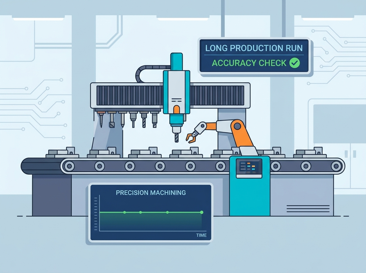
How Can a Linear Machining Center Maintain Accuracy in Long Production Runs?
Views: 0 Author: Site Editor Publish Time: 2026-08-22 Origin: Site
![facebook sharing button]()
![twitter sharing button]()
![line sharing button]()
![wechat sharing button]()
![linkedin sharing button]()
![pinterest sharing button]()
![whatsapp sharing button]()
![sharethis sharing button]()
Holding a tight tolerance on the first part off the machine is standard practice. Holding that exact same tolerance on the 10,000th part without an operator touching the dial is the true test of machine capability. High-volume manufacturing exposes the harsh operational reality of continuous production. Extended cycles compound thermal drift, mechanical vibration, and tool wear. These factors inevitably lead to scrapped parts, create quality assurance bottlenecks, and erode profit margins.
Modern linear way systems offer specific architectural advantages to solve these problems. Specific mechanical and software features mitigate accuracy degradation during continuous, multi-shift operations. A well-engineered machine manages heat effectively, absorbs harmonic vibrations before they reach the workpiece, and monitors tool degradation in real time. We will evaluate how specific mechanical and software features in these machines mitigate accuracy degradation during continuous, multi-shift operations.
Thermal Stability is the Baseline: Continuous operation generates heat; linear guideways and thermally compensated spindles minimize friction-induced expansion.
Repeatability Enables Compensation: A machine must first be repeatable. Predictable kinematic behavior allows advanced CNC software to automatically offset micro-errors over time.
Tool Management Dictates Uptime: Integrated linear tool changers reduce mechanical complexity and cycle times, directly impacting long-run consistency.
Structural Damping is Non-Negotiable: Robust gantry frames and optimized casting materials are required to absorb cutting forces and prevent vibration-induced tolerance drift.
Setup Reduction Preserves Tolerances: Utilizing multi-axis configurations minimizes manual part handling, eliminating tolerance stacking across long runs.
The Mechanics of Accuracy Drift in High-Volume Production
You must establish the difference between absolute accuracy and repeatability before evaluating any machine tool. Absolute accuracy means hitting the exact programmed coordinate in 3D space. Repeatability means hitting that same coordinate consistently over thousands of cycles. A machine can be inaccurate but highly repeatable. If you program a hole at X100.00mm and the machine drills it at X100.05mm every single time, it is repeatable. You can simply apply a -0.05mm offset in the controller, and the machine will hit the perfect dimension. If the machine drills at X100.05mm, then X99.92mm, then X100.11mm, it lacks repeatability. Software cannot fix unpredictable mechanical slop. High-volume production demands exceptional repeatability to sustain part quality.
Continuous spindle operation at high RPMs transfers massive amounts of heat to the machine casting. Spindles running at 20,000 to 24,000 RPM generate intense thermal loads in the ceramic bearings. This heat transfers into the spindle cartridge and migrates up into the Z-axis ram. Cast iron expands at roughly 11 to 12 micrometers per meter for every degree Celsius of temperature increase. Over a four-hour heavy roughing cycle, a five-degree temperature shift causes significant volumetric expansion across the machine structure. This expansion physically shifts the tool center point away from its programmed position. Unmanaged thermal growth destroys tight press-fit tolerances over a long shift.
Harmonic resonance and continuous cutting forces also degrade surface finish. Mechanical fatigue sets in during extended production cycles. Every time a cutting edge strikes the material, it sends a shockwave through the spindle, up the Z-axis, and into the gantry. Poorly damped machines amplify these vibrations over time. If the natural frequency of the machine frame matches the tooth-pass frequency of the cutter, harmonic resonance occurs. This resonance leads to visible chatter marks on the workpiece. It also causes dimensional accuracy to drift outside acceptable limits as the machine physically shakes itself out of alignment.
Tool degradation is an inevitable reality of continuous machining. Carbide cutting edges dull as they shear through abrasive materials. A dull tool increases cutting resistance, which pushes the tool away from the material. This deflection exacerbates runout and causes taper in deep pockets. A lack of automated monitoring allows this runout to go unnoticed until the operator pulls a bad part off the table. Operators eventually discover out-of-tolerance parts during final inspection, which means you have already wasted material and machine time. Automated tool measurement is necessary to catch degradation early and update offsets dynamically.
![CNC linear machining center spindle and gantry setup]()
Architectural Advantages of a CNC Linear Machining Center
Linear guideways offer distinct advantages over traditional box ways for high-speed routing and milling. You must evaluate the friction coefficient differences between the two systems. Box ways rely on sliding friction, which generates substantial heat at high feed rates. At low feed rates, static friction exceeds dynamic friction, causing a phenomenon known as stick-slip. The axis jumps slightly instead of moving in a fluid motion, which ruins the surface finish during circular interpolation. Linear ways utilize rolling contact through recirculating ball bearings or cylindrical rollers. This rolling contact drastically reduces heat generation and completely eliminates stick-slip. Linear guideways remain superior for sustained, high-speed accuracy.
Structural rigidity dictates how well a machine handles continuous cutting forces. Optimized damping in the machine frame is mandatory for long-run precision. Manufacturers use heavily ribbed cast iron or polymer concrete for the machine base. Polymer concrete, often called epoxy granite, absorbs vibrations up to ten times better than standard cast iron. A robust gantry frame absorbs continuous cutting forces and maintains geometric stability even under heavy chip loads. This rigidity prevents the gantry from twisting or racking during aggressive tool paths, ensuring the spindle remains perfectly perpendicular to the table.
Active thermal management is critical for high-performance spindle integration. Spindle cooling systems actively manage thermal loads during continuous duty cycles. Industrial chillers circulate a glycol-water mixture through a cooling jacket surrounding the spindle stator. This extracts heat before it can migrate into the Z-axis casting. Air and oil mist systems lubricate the ceramic bearings while providing additional cooling directly to the rotating components. Keeping the spindle at a constant, regulated temperature stabilizes the tool center point and prevents the Z-axis from growing during a long shift.
Integrating 5-axis capabilities reduces the need for manual part repositioning. Secondary setups introduce human error, clamping distortion, and mechanical misalignment. Eliminating these setups directly prevents tolerance stacking errors. A CNC Linear Machining Center can machine complex geometries, drill angled holes, and profile undercuts in a single clamping operation. Multi-axis configurations keep the part locked in its original coordinate system from the first cut to the final finishing pass. This setup reduction preserves tight tolerances during extended, multi-shift runs because the part never leaves the fixture.
Evaluating Tool Management for Continuous Operations
Tool management directly impacts long-run consistency and machine uptime. A linear tool changer router offers a simpler structural composition compared to complex carousel systems. Rack-style tool changers sit stationary at the end of the machine bed or under the gantry. They lack the complex cam mechanisms, Geneva drives, and swing arms found in umbrella styles. The gantry simply moves to the rack, deposits the current tool into an empty fork, moves to the next position, and engages the new tool. Fewer moving parts translate to higher mechanical reliability. This simplicity prevents alignment errors and dropped tools during thousands of automated tool changes.
Rapid and precise tool seating maintains Z-axis accuracy. A single speck of dust or a stray wood chip on the tool taper causes massive runout at the cutting edge. High-quality spindles use a high-pressure air blast through the center of the spindle to blow the taper clean during every single tool change. The drawbar mechanism must pull the tool holder into the spindle with consistent, immense force. Any variation in clamping force alters the tool length offset and reduces the stiffness of the tool assembly. Consistent tool seating ensures the cutting edge always returns to the exact programmed height, preventing gouged spoil boards or shallow cuts.
Automatic tool presetting detects wear before it impacts the workpiece. Laser measurement systems check tool length and diameter inside the machine envelope. They measure the tool while it spins at its actual operating RPM. This dynamic measurement accounts for centrifugal expansion, spindle runout, and actual cutting diameter. The system updates the tool offset table in the controller automatically. If a tool exceeds its predefined wear limit, the machine flags it for replacement and can automatically pull a redundant sister tool from the magazine. This automation prevents scrapped parts and broken cutters during unattended, lights-out shifts.
Software and Control Systems: The Brains Behind Repeatability
Modern controllers use thermal sensors placed strategically across the machine casting. These thermistors monitor temperature fluctuations in real time, feeding data back to the PLC. The control system uses this data to dynamically adjust axis positioning. This process is known as kinematic compensation. The software calculates the exact volumetric expansion of the frame based on the known thermal expansion coefficients of the casting materials. It then applies micro-offsets to the tool path on the fly.
For example, a machine might experience a predictable thermal drift of 0.03mm in the Y-axis as the shop heats up during the afternoon. The controller automatically applies a negative 0.03mm offset to counteract this expansion. The tool remains perfectly aligned with the workpiece coordinate system. The operator never has to stop the machine, pull out a dial indicator, or make manual adjustments. This real-time compensation is what makes continuous precision possible over a 24-hour production cycle.
Keeping CNC software and control firmware updated is a strict necessity. Firmware updates deliver the latest kinematic compensation algorithms developed by the manufacturer. They also refine vibration-dampening logic within the servo drives. Outdated firmware limits the machine's ability to process high-speed look-ahead blocks. Advanced look-ahead algorithms read thousands of lines of G-code in advance to smooth out aggressive tool paths. They decelerate the machine smoothly into tight corners and accelerate out of them, reducing mechanical shock and preserving the lifespan of the linear guideways.
Predictive maintenance relies on continuous spindle vibration monitoring. Load meters alert operators to mechanical anomalies before they cause a tolerance failure. A sudden spike in spindle load indicates severe tool wear, material inconsistency, or a packed chip flute. The controller can automatically pause the cycle, retract the tool, and alert the operator if vibrations exceed a safe threshold. This monitoring protects the expensive ceramic spindle bearings from catastrophic failure. It also ensures the machine only produces parts within the specified tolerance band.
Industry standards provide buyers with an objective evaluation lens. ISO 230-2 is the international standard used to verify accuracy and repeatability specifications in machine tools. It outlines specific testing protocols using laser interferometers to measure positioning errors along each axis. Buyers should always request documented ISO 230-2 test results before purchasing a machine. These standardized metrics cut through marketing claims. They reveal exactly how the machine will perform during a long production run, giving you hard data on its true repeatability.
Variables Impacting Continuous Machining Precision
Variable
Source of Error
Mitigation Strategy
Thermal Expansion
Spindle heat, ambient temperature swings
Active chillers, kinematic software compensation
Mechanical Vibration
Cutting forces, high-speed routing, harmonic resonance
Polymer concrete bases, robust gantry frames
Tool Degradation
Material shear, dulling carbide edges
Laser tool measurement, dynamic offset updates
Axis Friction
Stick-slip in sliding box ways
Rolling contact linear guideways
Application Focus: The Automatic Woodworking Machining Center
Woodworking presents unique challenges for maintaining continuous precision. Nesting and routing large panels require sustained accuracy across massive work envelopes. An automatic woodworking machining center must keep the gantry perfectly square over distances of ten feet or more. Dual-drive servo systems on the X-axis prevent racking. They utilize independent motors and encoders on each side of the gantry, ensuring both sides move in perfect synchronization. This electronic squaring sustains precision across large-format materials like MDF and plywood during continuous shifts.
Fine particulates pose a severe threat to linear guideways. High-speed routing generates massive volumes of abrasive dust that acts like sandpaper on moving parts. If this dust enters the bearing blocks, it destroys the recirculating balls and scores the steel rails. Advanced wiper systems physically scrape dust off the guide rails as the block moves. Positive air pressure inside the bearing blocks prevents particulates from entering the raceways. Double-lipped sealed bearings are an absolute necessity in these harsh environments to maintain positioning accuracy.
Vacuum hold-down systems also impact long-run accuracy. Large panels can warp, lift, or shift if vacuum pressure drops during aggressive routing. High-capacity rotary vane vacuum pumps secure the material flat against the spoil board. Z-axis accuracy relies entirely on the material remaining perfectly flat. If the board bows up by 0.5mm, your dado depth will be off by 0.5mm. Operators must surface the MDF spoil board regularly with a large fly cutter to maintain a true datum plane. Proper dust extraction keeps the vacuum zones clear of debris and maximizes hold-down force.
Implementation Risks and Operational Controls
Linear ways are generally easier to replace than traditional box ways, which require laborious hand-scraping. Maintenance often requires only screw removal, rail realignment, and torquing to spec. However, they require strict adherence to automated lubrication schedules. A failed automatic lubrication pump will destroy a linear rail in a matter of hours. Operators must verify oil or grease levels daily. They must also inspect the lubrication lines for pinhole leaks, crushed tubes, or blockages. Starved bearings increase friction, generate massive heat, and immediately degrade positioning accuracy.
Ambient shop temperature fluctuations represent a massive hidden risk to production. A machine cannot compensate for extreme environmental swings. If the shop temperature drops 15 degrees overnight, the machine casting will contract significantly. Software compensation algorithms assume a relatively stable baseline environment to calculate offsets accurately. Climate control is a prerequisite for long-run precision. Facilities must regulate ambient temperatures to keep thermal expansion predictable. You cannot expect a machine sitting next to an open bay door in winter to hold a tight tolerance.
Operator training directly impacts machine performance and longevity. You must train operators to interpret software offsets correctly and understand when a tool needs manual intervention. They need to understand how to manage tool life data within the controller, setting appropriate wear limits for different materials. Operators should know how to execute firmware updates safely without wiping machine parameters. They must also perform daily preventative maintenance routines, such as checking chiller fluid levels and cleaning tool tapers. A highly accurate CNC linear machining center will drift if the operator ignores spindle load warnings or bypasses automated tool measurement cycles to save time.
Conclusion
Request a physical test cut simulating a long production run before finalizing any machine purchase to verify real-world performance.
Ask vendors to provide documented thermal drift data and ISO 230-2 repeatability test results to validate their marketing claims.
Schedule a technical consultation to review your specific production tolerances, material types, and cycle times against the machine's capabilities.
Prioritize machines equipped with active spindle cooling, rolling contact linear guideways, and integrated laser tool measurement systems.
Implement strict climate control in your manufacturing facility to establish a stable baseline temperature for kinematic software compensation.
FAQ
Q: What is the difference between accuracy and repeatability in a CNC machining center?
A: Accuracy is the machine's ability to hit an exact programmed coordinate in space. Repeatability is the ability to hit that exact same coordinate consistently over thousands of cycles. Repeatability is crucial for long runs because it makes errors predictable. If a machine is repeatable, operators can use software offsets to correct the positioning and hold tight tolerances.
Q: How does thermal expansion affect a CNC linear machining center?
A: Continuous spindle operation generates intense heat. This heat transfers into the machine casting, causing volumetric growth. The expansion physically shifts the tool center point, ruining tight tolerances. Modern machines mitigate this using active spindle chillers and thermal sensors that feed data to kinematic compensation software to adjust the tool path dynamically.
Q: Why are linear guideways preferred over box ways for high-speed production?
A: Linear guideways use rolling contact, which creates significantly lower friction than the sliding contact of box ways. Lower friction reduces heat generation and completely eliminates the stick-slip phenomenon. This allows for faster, smoother axis movement and sustains high-speed positioning accuracy over long production shifts without excessive wear.
Q: How does a linear tool changer router improve production consistency?
A: Linear tool changers feature a simple rack-style design with fewer moving parts than complex carousel changers. This mechanical simplicity translates to higher reliability and fewer alignment errors. Faster cycle times and precise, reliable tool seating ensure the Z-axis remains accurate across thousands of automated tool changes.
Q: What maintenance is required to keep an automatic woodworking machining center accurate?
A: You must maintain strict automated lubrication schedules to protect the linear guideways from running dry. Dust extraction systems must operate at peak efficiency to remove abrasive particulates. Operators must regularly inspect and replace guideway wipers. Surfacing the spoil board frequently is also required to maintain a perfectly flat vacuum hold-down surface.
Q: Can software offsets completely fix an inaccurate CNC machine?
A: No. Software offsets can only compensate for predictable, repeatable errors, such as a consistent 0.03mm thermal drift. Software cannot fix mechanical slop, severe bearing wear, or unpredictable vibration caused by a weak frame. The machine must possess rigid mechanics and high repeatability before software compensation can be effective.

![English]()
![zhifufuben]()