-
- CNC Panel SawCNC Router MachineAutomatic Edge Banding MachineSix Sided CNC Drilling Machine
- Application
![news]()
How Should Side Aligners and Feed Clamps Be Calibrated on a Precision Panel Saw?
Views: 0 Author: Site Editor Publish Time: 2026-08-14 Origin: Site
![facebook sharing button]()
![twitter sharing button]()
![line sharing button]()
![wechat sharing button]()
![linkedin sharing button]()
![pinterest sharing button]()
![whatsapp sharing button]()
![sharethis sharing button]()
Cut quality in industrial woodworking relies heavily on material positioning. Blade sharpness alone cannot compensate for microscopic deviations in material handling mechanisms. These small errors compound quickly, causing significant squaring defects, undue stress on machine components, and dangerous kickback scenarios. When side aligners and feed clamps fall out of alignment, shops face immediate part rejection, assembly bottlenecks, and excessive material waste. Basic blade-to-fence alignment checks fall short for automated, high-throughput operations. Operators must systematically calibrate both pneumatic and mechanical positioning systems to maintain strict manufacturing tolerances. We will detail the technical protocols for aligning side aligners and feed clamps to ensure repeatable accuracy on a High Precision Panel Saw. You will learn how to establish reference planes, regulate pneumatic pressure, and integrate mechanical truth with software offsets.
Tolerance Baselines: Industrial calibration requires achieving runout tolerances of 0.1mm (0.005 inches) or less; standard DIY calibration hacks are entirely insufficient for this level of precision.
Sequential Alignment: Feed clamp zero-point calibration must always follow the verification of blade parallelism, scoring motor coupling, and pusher fence squareness.
Mechanical vs. Digital: On a computer controlled beam saw, physical mechanical alignment must be perfected before adjusting software encoder offsets.
Pressure Regulation: Proper calibration includes setting appropriate pneumatic pressure for side aligners to prevent material deflection, edge damage, or chassis strain during the squaring cycle.
The Role of Material Handling in a High Precision Panel Saw
Absolute dimensional accuracy defines the operational requirement for industrial cutting equipment. A successful calibration yields perfectly square panels. These panels must measure exactly 90 degrees at every corner. They must also exhibit zero tapering across maximum cut lengths. Achieving this requires flawless material handling mechanisms. When a panel stack enters the cutting zone, it carries significant mass. The material handling system must control this mass with absolute rigidity.
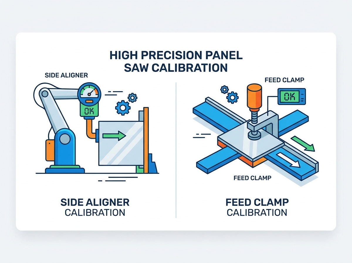
Side aligners function as pneumatic or motorized rollers. They press the book of panels against the crosscut fence. This action ensures perfect right angles before the pressure beam descends. Feed clamps operate as grippers attached to the pusher system. They advance the material through the cutting axis for rip cuts. Both components must work in perfect synchronization. If the side aligner applies uneven pressure, the stack pivots slightly. This pivot creates an immediate taper along the cut line.
Precision in these two components directly translates to superior manufacturing outcomes. Accurate feed clamps reduce kickback risks significantly by keeping the material parallel to the blade body. Perfectly aligned side aligners extend tooling life by preventing lateral blade friction. These factors create safe cutting environments. They also eliminate the need for downstream CNC routing corrections. When a high precision panel saw operates with calibrated material handlers, production efficiency peaks.
Poor material handling manifests in several distinct cutting defects. Operators should watch for these specific failure points:
Tapered rip cuts caused by uneven clamp pressure across the pusher beam.
Chipped trailing edges resulting from material shifting during the saw carriage return stroke.
Premature wear on the main saw blade due to lateral friction against the panel edge.
Inconsistent scoring lines that fail to match the main kerf width.
Burn marks on dense materials like phenolic resin or hard maple.
Pre-Calibration Diagnostics and Tooling Requirements
Before adjusting material handlers, operators must establish the absolute foundational reference plane. You must verify the machine's primary guide rails. Alternatively, use the sliding table guide. This plane dictates every subsequent measurement. Do not skip this diagnostic phase. Dirt, resin buildup, or physical damage on the guide rails will throw off every dial indicator reading you take. Clean the linear bearings and rails thoroughly with a non-corrosive solvent before mounting any measurement tools.
Establish baseline verification next. The main saw blade must sit perfectly parallel to the reference plane. The scoring blade requires the exact same parallelism. Check the scoring motor coupling for physical play. Loose couplings often mimic clamp alignment issues. Grab the scoring blade body and attempt to rotate it back and forth. If you feel a distinct click or movement before the motor shaft engages, the coupling spider needs replacement. Resolve any blade runout before touching the material handling systems.
Industrial calibration demands specific instrumentation. You need industrial-grade dial indicators with magnetic bases. Procure precision machinist squares rated at DIN 875 Grade 00. Keep high-end digital calipers and feeler gauges on hand. Explicitly discard low-cost DIY table saw calibration methods. Techniques under twenty dollars are entirely inadequate for industrial beam saws. A standard framing square will not provide the resolution needed to hit a 0.1mm tolerance over a three-meter span.
Safety protocols require strict adherence. Implement comprehensive lockout/tagout (LOTO) procedures immediately. You must isolate all pneumatic lines before initiating mechanical adjustments. This prevents accidental actuation of the pressure beam or feed clamps. Secure the machine state before applying any wrenches. Bleed the residual air from the pneumatic manifolds to ensure the cylinders cannot fire unexpectedly.
Calibration Tooling Specifications
Tool Type
Required Specification
Primary Application
Dial Indicator
0.01mm resolution, magnetic base
Measuring blade parallelism and aligner runout
Machinist Square
DIN 875 Grade 00
Verifying pusher beam and crosscut fence squareness
Digital Caliper
300mm length, 0.01mm accuracy
Measuring 5-cut method offcuts and kerf width
Feeler Gauges
0.02mm to 1.00mm range
Checking feed clamp jaw clearance
Torque Wrench
10Nm to 100Nm range
Securing carriage bolts to factory specifications
![High Precision Panel Saw Calibration]()
Step-by-Step Calibration of Side Aligners
Squaring the Aligner to the Cutting Line
Mechanical alignment begins at the saw carriage. Mount a dial indicator securely to the carriage assembly. Position the indicator tip against the side aligner fence. Traverse the carriage along the cutting axis. Measure the parallelism of the side aligner fence against the guide rails. Adjust the aligner mounting bolts until runout drops below 0.05mm across the full travel distance. Lock down the hardware and run the carriage back and forth three times to verify the setting holds under vibration.
Adjusting the stroke requires setting precise travel limits. Configure the minimum and maximum extension of the aligner. It must accommodate different panel widths accurately. Prevent the pneumatic cylinders from bottoming out. Hard impacts place undue stress on the machine chassis and eventually destroy the cylinder seals. Set the mechanical stops to engage just before the cylinder reaches its physical limit. This transfers the impact force to the solid steel chassis rather than the delicate internal piston.
Regulating Pneumatic Pressure and Timing
Pressure calibration protects your material inventory. Adjust the air pressure regulators carefully. The aligner must apply sufficient force to move heavy panel books. However, it must not crush delicate laminates. Excessive pressure causes edge banding blowouts and compresses the core material. Test the pressure on scrap material first. Dial the regulator down to the lowest effective pressure setting that still pushes the stack flush against the crosscut fence without hesitation.
Sequence timing ensures safe clamping operations. The side aligner must engage the material completely. It must fully seat the panel book against the crosscut fence. This action must finish before the main pressure beam clamps down. Adjust the pneumatic flow control valves to sequence these movements. Delay the pressure beam descent by a fraction of a second if necessary. If the pressure beam drops while the aligner is still moving the material, the panel will skew, ruining the cut.
Verifying 90-Degree Crosscut Accuracy
The 5-cut method validates your mechanical adjustments. Adapt this standard squaring test for large-scale panel saws. Use a large test panel, ideally 1000mm by 1000mm. This method measures accumulated error over a wide surface area, magnifying microscopic deviations so you can measure them easily with digital calipers.
Load a test panel measuring at least 1000mm by 1000mm onto the machine table.
Make the first trim cut and label the newly cut edge as side one.
Rotate the panel clockwise, placing side one directly against the crosscut fence.
Execute the second cut, labeling the new edge as side two.
Repeat this rotation and cutting process for sides three and four.
Rotate one final time and cut a 20mm strip off side one.
Measure the top and bottom width of this final offcut strip using digital calipers.
Calculate the tolerance using the final offcut. Measure the thickness at both ends of the offcut strip. Subtract the smaller measurement from the larger one. Divide this difference by four. This gives you the error per cut. Divide again by the length of the cut to find the error per meter. Aim for a deviation of less than 0.05mm per 1000mm. If the error exceeds this limit, you must re-adjust the crosscut fence and side aligner parallelism.
Calibrating Feed Clamps on a Computer Controlled Beam Saw
Parallelism Between Clamps and the Cutting Axis
Leveling the grippers prevents surface damage. Check the lower jaws of all feed clamps. They must sit perfectly flush with the machine table. Use a straightedge across the table surface. Adjust the clamp mounting brackets vertically. Misaligned jaws cause material lifting during the cut. If the lower jaw sits even 0.5mm above the table, it lifts the panel, changing the effective cutting angle. They also scratch delicate melamine surfaces during retraction when the pusher beam returns to the home position.
Squaring the pusher beam dictates rip cut accuracy. Use a precision square and a dial indicator. Ensure the entire pusher beam housing the clamps sits exactly 90 degrees to the cutting line. Loosen the main mounting bolts on the pusher carriage. Tap the beam gently into alignment using a dead blow hammer. Lock down the hardware and verify the measurement again. A pusher beam that sits out of square will force the feed clamps to push the material at an angle, causing severe binding against the saw blade.
Zero-Point Calibration for the Pusher Fence
Establishing the origin synchronizes the machine dimensions. Bring the feed clamps forward mechanically. Move them to the absolute zero position relative to the saw blade kerf. Use a precision feeler gauge between the clamp jaw and the main blade body. Do not measure against the carbide teeth, as tooth width varies between blade models. This establishes the physical zero point for the pusher system. Lock the clamps in this position and reset the encoder value to zero in the control software.
Kerf and scoring compensation prevent dimension errors. Factor in the exact thickness of the main saw blade. Ensure the scoring blade kerf perfectly matches the main blade width. If the scoring blade cuts wider, you get stepped cuts on the first trim pass. Adjust the scoring blade shims or electronic width settings accordingly. Measure the actual kerf width by making a test cut in scrap material and measuring the slot with digital calipers. Enter this exact value into the machine's tool library.
Clamp Pressure and Material Sensors
Sensor calibration ensures reliable automated cycles. Adjust the optical or mechanical sensors located within the clamps. These sensors detect panel presence and measure material thickness. Clean the sensor lenses thoroughly with isopropyl alcohol. Adjust the sensitivity thresholds. The clamps must recognize thin laminates just as easily as thick MDF boards. If the sensors fail to detect the material, the machine will halt the cycle and throw a safety fault.
Variable pressure settings protect fragile core materials. Calibrate the proportional valves controlling the clamp cylinders. Reduce clamp pressure for honeycomb cores or thin MDF. High pressure crushes these materials, altering the cut dimensions and damaging the panel edges. Program specific pressure profiles for different material types within the machine control software. This allows the operator to switch between solid wood and delicate composites without manually adjusting pneumatic regulators.
Recommended Feed Clamp Pressure Profiles
Material Type
Density Range
Recommended Pressure (bar)
Sensor Sensitivity
High-Density Fiberboard (HDF)
800+ kg/m³
6.0 - 7.0
Standard
Standard MDF / Particleboard
600 - 800 kg/m³
4.5 - 5.5
Standard
Plywood (Softwood Core)
400 - 600 kg/m³
3.5 - 4.5
High
Honeycomb / Hollow Core
Under 400 kg/m³
2.0 - 3.0
Maximum
Servo Panel Cutting Machine Integration: Software vs. Mechanical Adjustments
Encoder Calibration and Digital Offsets
Digital translation bridges the physical and electronic systems. The machine's PLC interprets the physical position of the servo drives via rotary encoders. These encoders count electrical pulses to determine exact locations along the linear rails. Verify that the physical distance moved matches the distance displayed on the control screen. Use a calibrated tape measure for macro verification. Command the pusher beam to move exactly 1000mm. Measure the actual travel distance. If the physical movement measures 1002mm, you must adjust the encoder scaling factor in the machine parameters.
Inputting offsets requires strict discipline. Only use software offsets in the HMI to correct micro-deviations. You must achieve mechanical squareness first. Never use digital offsets to mask a physically misaligned pusher beam. Enter the exact kerf compensation values. Update these offsets every time you change the saw blades on your computer controlled beam saw. Relying on software to fix mechanical problems leads to diagonal cutting inaccuracies and forces the servo motors to fight against the physical binding of the linear guides.
Mechanical Backlash Compensation
Identifying backlash prevents positioning inconsistencies. Measure play in the rack and pinion or ball screw systems driving the pusher fence. Place a dial indicator against the pusher beam. Push and pull the beam manually using a small pry bar. Note the movement on the indicator before the servo motor resists. This measurement represents your mechanical backlash. Even high-end systems develop slight backlash over thousands of operating hours as gear teeth wear down.
Software compensation neutralizes this mechanical play. Enter the measured backlash values into the control software. The system will now overdrive the target position slightly and reverse into it. This ensures the servo panel cutting machine positions accurately regardless of the approach direction. Monitor backlash values monthly, as gear wear increases play over time. If the backlash exceeds 0.5mm, software compensation becomes unreliable, and you must replace the worn mechanical components.
Troubleshooting Common Alignment Errors
Lateral binding and kickback present severe safety hazards. Diagnose feed clamps that sit out of parallel. When clamps push material at an angle, the panel pinches the rising blade. This creates dangerous kickback scenarios. It also reduces blade life through excessive lateral friction. Re-square the pusher beam immediately if you detect burn marks on rip cuts. Listen to the machine during the cut. A distinct whining noise or heavy motor lugging often indicates the material is binding against the side of the blade body.
Scoring motor coupling issues often masquerade as clamp problems. You may notice stepped cuts or bottom-edge chipping. These defects might persist even after feed clamp zeroing. Trace this back to mechanical play in the scoring motor coupling. Replace worn polyurethane spiders in the coupling assembly. Tighten all set screws on the scoring motor shaft. If the offcut shows a heavy score line on the bottom face but the top face is clean, the scoring blade is shifting laterally during the cut due to a loose coupling.
Guide rail wear versus aligner error requires careful differentiation. Persistent squaring issues stem from two main sources. Determine if the problem is a miscalibrated side aligner. Alternatively, check for physical wear or debris on the sliding table guide rails. Clean the linear bearings thoroughly. If the rails show visible grooving or pitting, mechanical alignment will not hold. You can calibrate the aligner perfectly, but the carriage will still deflect when it rolls over a damaged section of the guide rail.
Implementation Risks and Maintenance Trade-offs
The risk of over-tightening compromises machine longevity. Applying excessive torque on clamp gibs or aligner bearings causes premature wear. It strains the servo motors during rapid positioning moves. Binding occurs when linear guides lack proper clearance. Follow the manufacturer's exact torque specifications. Use a calibrated torque wrench for all critical carriage bolts. Overtightening the gibs on the pusher beam will cause the servo drives to draw excessive amperage, eventually triggering thermal overload faults in the electrical cabinet.
Environmental factors degrade calibration accuracy rapidly. Dust accumulation coats optical sensors, causing false readings. Fine particulate matter infiltrates pneumatic cylinder seals. This leads to pressure drops and phantom alignment errors. Implement aggressive dust extraction protocols. Ensure the dust collection system pulls adequate CFM at the machine ports. A drop in shop air pressure can also cause the side aligners to fail mid-cut. Verify that your air compressor provides a consistent 6 to 8 bar of clean, dry air to the machine's pneumatic manifold.
Maintain a strict schedule to prevent calibration drift. Operators should perform these checks regularly:
Wipe down all sensor lenses with isopropyl alcohol daily.
Drain moisture traps on the pneumatic supply lines weekly.
Inspect feed clamp rubber pads for uneven wear monthly.
Verify pusher beam squareness after any severe material jam.
Check the torque on all major carriage bolts quarterly.
Conclusion
Consistent calibration of side aligners and feed clamps remains non-negotiable for maintaining high-end cutting equipment. Mechanical truth must always precede software correction. Never rely on digital offsets to fix physical misalignments. Proper pressure regulation and precise zero-point calibration guarantee square panels and safe operations. For facilities experiencing constant alignment drift, evaluate your current hardware. Determine whether the machine's chassis lacks the rigidity for high-volume work. Frequent loss of calibration signals structural fatigue. Execute the following steps to secure your production tolerances.
Implement a documented monthly calibration log to track mechanical drift.
Invest in precision measurement tooling, including Grade 00 machinist squares.
Schedule a comprehensive baseline audit with a certified factory technician.
Standardize pneumatic pressure settings for different material densities.
FAQ
Q: What is the acceptable runout tolerance for industrial panel saws?
A: Industrial standards dictate a runout tolerance of 0.1mm or less over a 1000mm cut length. Achieving this requires precision dial indicators and strict adherence to mechanical squaring protocols. Standard DIY methods cannot achieve or measure this level of accuracy reliably.
Q: Why do I get stepped cuts even after zeroing the feed clamps?
A: Stepped cuts usually indicate a mismatch between the main blade and the scoring blade kerf. It can also stem from mechanical play in the scoring motor coupling. Verify that the scoring blade width exactly matches the main blade and check the coupling for wear.
Q: How often should side aligners be calibrated?
A: Perform a basic 5-cut squaring check weekly. Conduct a full mechanical calibration using dial indicators monthly, or immediately following any severe machine impact, blade crash, or major preventative maintenance teardown.
Q: Can I use software offsets instead of mechanical alignment?
A: No. Software offsets should only correct micro-deviations after you achieve physical mechanical squareness. Using digital offsets to mask a misaligned pusher beam causes compound errors, diagonal cutting inaccuracies, and excessive wear on linear guides.
Q: What causes feed clamps to scratch the material surface?
A: Scratches occur when the lower jaws of the feed clamps are not perfectly flush with the machine table. Misaligned jaws lift the material slightly during clamping or drag across the surface during retraction. Level the clamp brackets vertically to resolve this.
Q: How do I prevent delicate laminates from crushing during alignment?
A: Adjust the pneumatic pressure regulators for the side aligners and feed clamps. Dial the pressure down to the lowest setting that still reliably moves the panel book. Use proportional valves to program specific, lower-pressure profiles for fragile core materials.

![English]()
![zhifufuben]()