-
- CNC Panel SawCNC Router MachineAutomatic Edge Banding MachineSix Sided CNC Drilling Machine
- Application
![news]()
How Should Spindles Be Assigned on a Four Process CNC Cutting Machine?
Views: 0 Author: Site Editor Publish Time: 2026-10-30 Origin: Site
![facebook sharing button]()
![twitter sharing button]()
![line sharing button]()
![wechat sharing button]()
![linkedin sharing button]()
![pinterest sharing button]()
![whatsapp sharing button]()
![sharethis sharing button]()
Are you struggling to balance production speed and cutting precision on a bustling factory floor? For many mid-sized furniture manufacturers, the financial leap to a fully automated Automatic Tool Changer system feels out of reach. Conversely, relying on manual tool changes leads to agonizing production bottlenecks and operator fatigue. Enter the four process CNC cutting machine, an ingenious middle-ground solution engineered to bridge this exact gap.
Simply owning the equipment is only half the battle. If your tools are improperly set up, you will inevitably face unnecessary machine idling, premature bit wear, and ruined sheet materials. In this comprehensive engineering guide, we will explore the precise methodology for assigning spindles. This practical approach will help you maximize operational efficiency and secure a much faster return on investment.
Key Takeaways for Factory Managers
Spindle 1 Main Cutting: Typically assigned a high-power compression bit for cutting out main panel shapes. This task demands the most horsepower and structural stability.
Spindle 2 Grooving and Dadoing: Reserved for smaller diameter bits to create back-panel grooves. Keeping a dedicated bit prevents dulling the primary cutting tool.
Spindle 3 Drilling and Hinges: Fitted with a specialized bit for hardware holes like hinge cups and cam locks. Dedicated drilling prevents burn marks and ensures vertical accuracy.
Spindle 4 Detailing and Secondary Drilling: Used for lighter detailing, secondary hole sizes, or edge profiling. This provides crucial flexibility without interrupting the main workflow.
Efficiency Boost: Proper assignment eliminates manual tool changes, making this equipment ideal for high-volume cabinet nesting operations.
Understanding the Multi-Spindle Architecture
When scaling up daily operations, shop owners frequently hit a production wall with standard single-spindle routers. To circumvent this limitation, equipment manufacturers developed a specialized architecture. It offers rapid tool switching without the steep cost and mechanical fragility of a traditional tool magazine.
The Mechanics of Instant Tool Switching
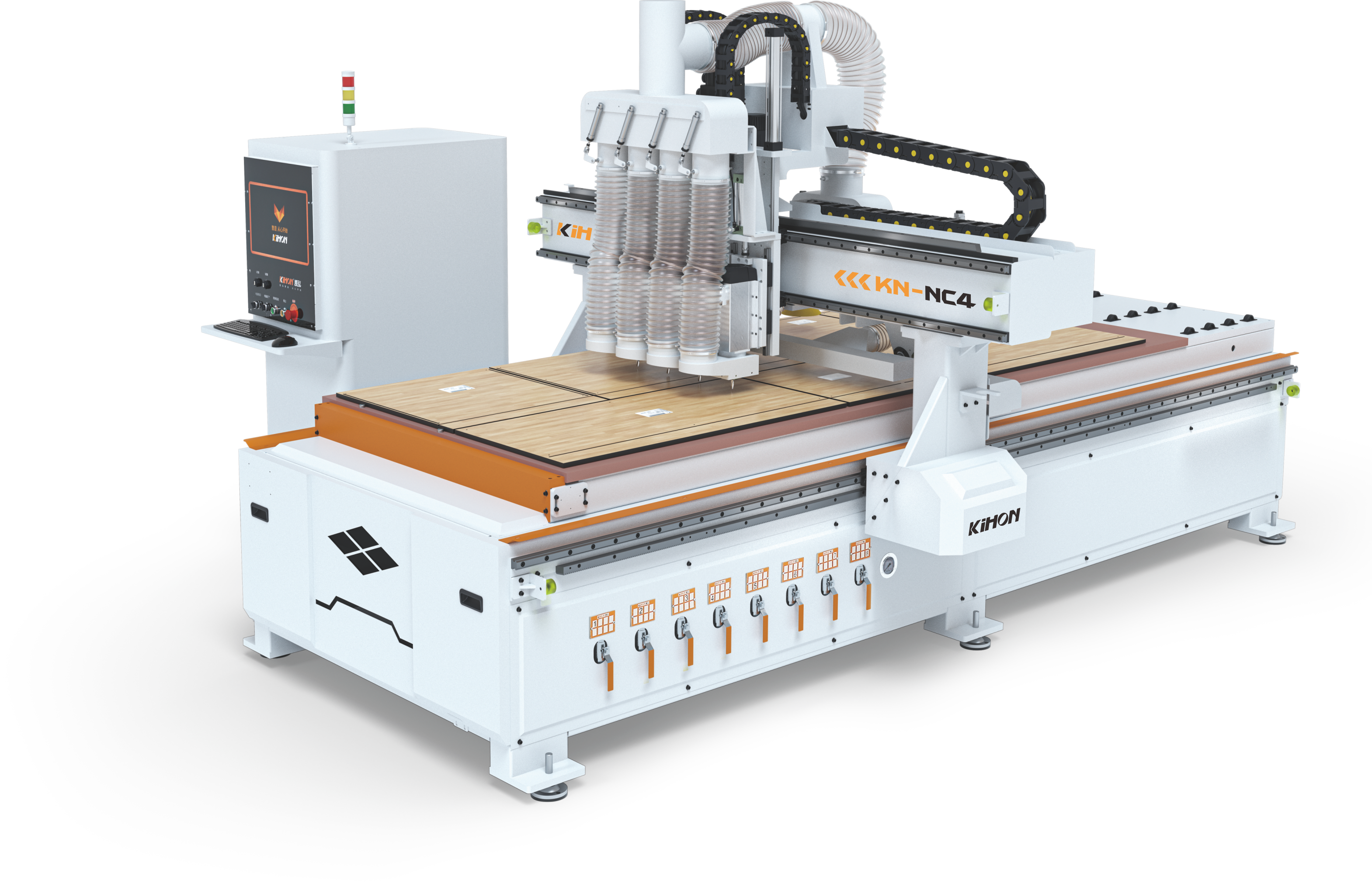
Instead of utilizing a single spindle that must physically travel across the gantry to a distant tool rack, a multi spindle woodworking router houses four independent spindles mounted directly on the Z-axis carriage. Each spindle holds a specific, pre-calibrated router bit.
The magic happens through a highly responsive pneumatic cylinder system. When the generated G-code calls for a new operation, the active spindle retracts upward. Simultaneously, the corresponding pneumatic cylinder instantly plunges the next required tool into the cutting position. This seamless transition takes less than two seconds. Consequently, cycle times drop drastically compared to manual swapping.
The Ultimate Solution for Panel Furniture
This specific configuration is tailor-made for processing engineered woods like MDF, plywood, and melamine-faced particleboard. In the realm of custom cabinetry and wardrobe production, a standard sheet of material generally demands exactly four distinct operations. These include cutting the outer perimeters, milling shallow grooves for back panels, drilling structural hardware holes, and adding minor aesthetic details.
By executing these four tasks in a single uninterrupted flow, the equipment serves as a highly effective cabinet panel nesting machine. It is perfectly optimized for flat-pack furniture manufacturing.
The Strategic Logic Behind Spindle Assignment
Assigning tools to your spindles is far from a random guessing game. It requires a nuanced understanding of machine mechanics, material behavior, and workflow optimization.
Looking at recent shifts in the woodworking industry, there is a clear trend toward mass customization. We often refer to this as high-mix, low-volume manufacturing. As skilled labor becomes scarcer and wages rise, mid-sized shops are being forced to automate. Industry analyses indicate that while massive factory floors lean heavily into robotic cells, the mid-market is aggressively adopting multi-spindle architectures. The ability to instantly swap between four core tools aligns perfectly with the standard 32mm European cabinet system. This market shift highlights a pragmatic, highly profitable balance between automation and affordability.
Reducing Machine Idle Time
The primary goal of a multi-spindle setup is to minimize non-cutting movements. If tools are assigned poorly, the machine may perform unnecessary Z-axis travel or redundant sweeps across the X and Y axes. By strategically grouping the most frequently used tools, operators ensure the machine transitions from one operation to the next with minimal travel distance. Ultimately, this logical sequencing translates to faster sheet processing times and a significantly higher daily output.
Managing Spindle Wear and Tear
Not all spindles on these machines are identical. In proven industrial configurations, manufacturers install a high-power spindle alongside lower-power units. The heaviest tasks, such as full-depth profile cutting through dense 18mm birch plywood, generate immense radial loads and heat. Specifically, these roughing tasks must be assigned to the spindle with the highest horsepower rating and the most robust ceramic bearings. Assigning a heavy load to a lighter spindle will inevitably result in premature bearing failure and screeching tool runout.
Optimizing Dust Collection Efficiency
Dust extraction is a critical yet often overlooked component of CNC operation. The dust hood on a four-process machine is designed to encompass all four spindles, but internal airflow dynamics shift depending on which spindle is lowered. Assigning the heaviest dust-producing tools to the spindles closest to the primary vacuum port can drastically improve chip evacuation. This keeps the material surface clean and prevents the bit from grinding through its own sawdust.
![Four Process CNC Cutting Machine Configuration]()
Step-by-Step: The Standard Spindle Assignment for Cabinet Making
For standard panel furniture, the engineering community has developed a highly optimized tool assignment protocol. This layout covers approximately 90 percent of daily cabinet-making requirements. It allows operators to process full sheets of material without ever pausing the machine.
Spindle 1: The Heavy-Duty Cutter
Tool: 8mm or 10mm Compression Spiral Bit.
Function: Cutting the outer profiles of the cabinet panels and sizing the nested parts.
Why: The main cutting operation handles the vast majority of material removal. A compression bit features both up-cut and down-cut flutes, which compress the wood fibers toward the center of the cut. This mechanical action guarantees crisp, splinter-free edges on delicate melamine or wood veneer surfaces. Because this bit plows through the entire thickness of the board, it demands the most power. Therefore, Spindle 1 should always be your primary, highest-horsepower motor.
Spindle 2: The Grooving Specialist
Tool: 6mm or 8mm Straight or Down-cut Bit.
Function: Cutting shallow dadoes for cabinet back panels or drawer bottoms to securely slide into.
Why: Grooving requires a clean top edge but rarely penetrates more than 6mm into the material. Using a down-cut bit ensures the top surface remains pristine. Furthermore, reserving Spindle 2 strictly for grooving ensures that this specific bit remains razor-sharp. Attempting to use the main compression bit for shallow dadoes would cause continuous friction, prematurely destroying the bottom tip of your most expensive tool.
Spindle 3: The Primary Driller
Tool: 15mm Hinge Boring Bit or 8mm Brad Point Bit.
Function: Drilling precise, clean holes for hinges, cam locks, wooden dowels, and ready-to-assemble fittings.
Why: Hardware installation requires perfectly vertical holes with flat or precisely angled bottoms. A dedicated drilling bit on Spindle 3 prevents the acrid smell of burning wood and the ugly tear-out that occurs if you try to plunge a standard routing bit into a panel. Brad point bits feature a sharp center spur that prevents the tool from wandering. This ensures your hardware aligns flawlessly during final assembly.
Spindle 4: The Secondary Driller or Engraver
Tool: 5mm V-Nail Bit, Shelf Pin Drill, or V-Groove Router Bit.
Function: Drilling small 5mm holes for adjustable shelf pins, or engraving decorative lines on cabinet doors.
Why: The fourth spindle provides the crucial flexibility needed for custom project requirements. Adjustable shelving is a staple in modern cabinetry. A dedicated 5mm drill bit can rapidly plunge hundreds of shelf pin holes across a nested sheet in seconds. Alternatively, if the project involves decorative MDF shaker doors, this spindle can hold a V-bit for intricate detailing without disrupting the primary cutting workflow.
Alternative Configurations for Custom Woodworking
While the standard cabinet setup is undeniably efficient, the four-process architecture is versatile enough to handle highly specialized woodworking tasks. By simply swapping the tool loadout, shops can entirely pivot their production focus.
Setup for Wooden Door Manufacturing
Manufacturing solid wood or thick MDF interior doors requires a completely different approach to material removal and edge profiling.
Spindle 1: A heavy roughing bit for rapid material removal and hogging out large pocket areas.
Spindle 2: A large-diameter profiling bit to create sweeping, decorative edge details around the perimeter of the door.
Spindle 3: A specialized lock-hole milling bit designed for deep plunging to create mortises for door handles and internal hardware.
Spindle 4: A delicate V-bit or ball nose bit for intricate decorative carving on the face of the panel.
Equipment Comparison: Finding the Engineering Sweet Spot
For production managers and business owners, selecting the right machinery requires a rigorous analysis of production volume, initial capital expenditure, and long-term return on investment. This multi-spindle equipment occupies a highly specific middle ground in the market.
Compared to a Single Spindle CNC Router
A standard single-spindle CNC router is the most cost-effective entry point for digital woodworking. However, its primary limitation lies in its operational workflow. Every time a new tool is required, the machine must come to a complete, grinding halt. The operator must manually loosen the collet, replace the hot tool, recalibrate the Z-axis zero point, and finally restart the cutting sequence.
Manual tool changes can consume up to 40 percent of total production time during complex cabinet nesting. Furthermore, there is a much higher risk of human error during manual Z-axis recalibration. This leads to inconsistent cut depths and increased operator fatigue.
Compared to an Automatic Tool Changer System
An advanced system uses a single spindle equipped with a tool magazine that holds anywhere from 8 to 16 tools. When a tool change is required, the spindle travels to the magazine, deposits the current tool into a fork, and retrieves the next one.
While offering unmatched flexibility for complex architectural millwork, it requires a substantially higher initial investment. In addition, tool change times still take 8 to 15 seconds as the heavy gantry must physically travel across the bed. The complex servo-driven moving parts also increase the probability of mechanical failure if not meticulously maintained.
The Verdict for Cabinet Makers
The four-process machine utilizes a pneumatic cylinder system to drop the required spindle instantly. Because the tools are pre-loaded on independent motors, switching takes less than two seconds and requires absolutely no gantry travel. For approximately 80 percent of standard panel furniture manufacturing, four tools are entirely sufficient. As a result, it stands as the most mathematically sound investment for mid-sized cabinet shops looking to scale up.
Technical Feature
Single Spindle CNC
Four Process CNC
Automated Magazine CNC
Tool Change Method
Manual Wrench
Direct Pneumatic Drop
Gantry Travel to Magazine
Tool Change Time
2 to 5 Minutes
Under 2 Seconds
8 to 15 Seconds
Mechanical Complexity
Low
Medium
High
Optimal Application
Custom Prototypes
High-Volume Panel Nesting
Complex 3D Millwork
Software Integration and Post-Processing
The robust physical hardware of a multi-spindle router is only as effective as the manufacturing software driving it. Efficient spindle assignment requires precise software integration to ensure the machine control brain knows exactly which pneumatic cylinder to trigger.
Modern panel processing relies heavily on dedicated cabinet design software. These intuitive platforms allow designers to create complete 3D kitchen layouts and automatically flatten the components onto standard sheet goods to maximize material yield. When configuring the post-processor, tool numbers are mapped directly to the controller M-codes. For instance, when the code reads T1, it triggers the pneumatic solenoid valve for Spindle 1 to descend. By mapping the tools correctly during the initial setup, the generated G-code automatically manages all spindle transitions seamlessly.
Engineering Standards for Choosing the Right Machine
Procuring the correct specification is critical to achieving a high ROI. When evaluating a nesting machine for your facility, focus on empirical engineering specifications rather than superficial marketing claims. Equipment like the KN-NC4 series provides an excellent baseline for what to look for.
Staggered Spindle Power Configuration
A highly efficient configuration is a staggered power setup. For example, Spindle 1 should be a robust 6.0kW unit to handle full-depth cuts without bogging down. Spindles 2, 3, and 4 can safely be 4.5kW units. This intelligent setup reduces the overall weight dragging on the Z-axis gantry while providing ample torque exactly where it is needed most.
Drive Motors: The AC Servo Advantage
For high-speed aggressive panel nesting, servo motors are strictly mandatory. Servo systems operate on a closed-loop feedback mechanism, meaning they constantly communicate their exact physical position to the controller. This absolutely prevents lost steps during rapid diagonal cutting maneuvers. AC servo motors provide superior acceleration, smoother cornering, and significantly higher positioning accuracy.
Vacuum Hold-Down Power
A nesting machine is entirely dependent on its ability to hold small lightweight parts stationary during aggressive routing. Look for a machine boasting a multi-zone vacuum table constructed from high-density phenolic material. Paired with a high-capacity vacuum pump boasting a minimum of 160 cubic meters per hour, this ensures that small drawer parts do not shift and get destroyed by the cutter.
Conclusion and Next Steps
While a multi-spindle architecture inherently boosts your factory production speed, realizing its full potential requires strategic spindle assignment. By dedicating specific spindles to heavy cutting, shallow grooving, precise drilling, and custom detailing, operators can ensure maximum workflow efficiency and drastically reduce expensive tool wear.
This intelligent engineering setup perfectly bridges the gap between the agonizing slowness of manual tool changes and the overwhelming expense of complex tool magazine systems. For the vast majority of modern panel furniture manufacturers, it remains the ultimate sweet spot for scaling up production safely and profitably. If you are ready to eliminate bottlenecks and optimize your shop floor, explore the robust solutions at Kihon Machine and contact our technical engineering team today to configure the perfect equipment for your manufacturing needs.
Frequently Asked Questions
Can I use this machine configuration for deep 3D carving?
Yes, the machine control system is technically capable of 3D carving. However, the physical architecture is primarily engineered for 2D nesting and flat panel processing. The multi-spindle setup shines during rapid tool switching on flat sheet goods. For highly complex, deep 3D carving that requires massive Z-axis clearance, a dedicated single-spindle or 5-axis CNC router is generally a much better fit.
What happens if my custom cabinet design requires five different tools?
If a specific custom job requires more than four tools, the automated workflow is temporarily interrupted. You will need to program a manual pause in the G-code, physically wrench out the bit in one of the spindles, insert the fifth tool, recalibrate its Z-zero point, and resume the program. To maintain high efficiency, most engineers intentionally redesign their cabinet files to utilize exactly four tools.
Are the spindles typically air-cooled or water-cooled?
Most modern four-process machines utilize air-cooled spindles. Air-cooled systems are highly preferred in high-production woodworking environments because they require less daily plumbing maintenance, completely eliminate the need for external water chillers, and perform reliably in dusty conditions.
How fast can the pneumatic system switch between tools?
The tool switching process occurs almost instantaneously. Because the router bits are already securely loaded into their respective independent motors, the machine gantry does not need to travel to a distant magazine. The pneumatic cylinder system simply raises the active spindle and forcefully lowers the next required spindle in under two seconds.
What is the optimal feed rate for the main compression bit?
Optimal feed rates depend heavily on material density and spindle RPM. However, for a standard 6.0kW spindle running an 8mm compression bit through 18mm melamine, engineers typically recommend starting at a feed rate of 15 to 18 meters per minute at 18,000 RPM. Always monitor chip load and listen for spindle bogging to fine-tune these parameters.
How often should I calibrate the Z-axis for multiple spindles?
You must recalibrate the Z-axis zero point for a specific spindle every single time you change the router bit in that spindle. If your bits remain unchanged, a weekly verification using a digital tool setter is highly recommended to account for minute thermal expansion or mechanical settling across the gantry.

![English]()
![zhifufuben]()